Overview.
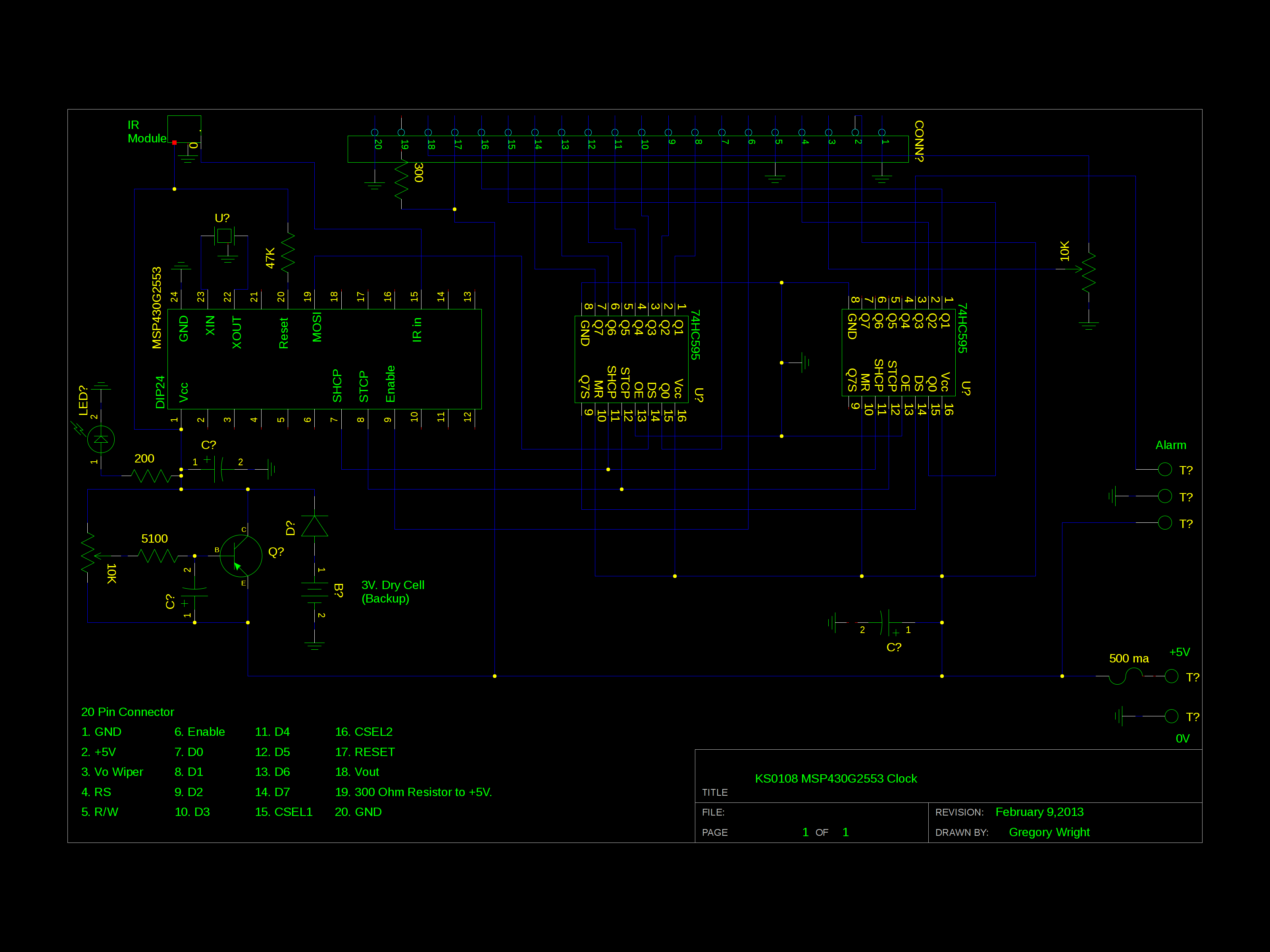
This clock uses a KS0108 chipset GLCD driven by a TI MSP430G2553 MCU via two 74HC595 shift registers. The crystal is a MS3V-T1R Micro Crystal. The remote control is a standard SONY remote.
Sony remotes use a 12 bit datastream which can be decoded faster than the 32 bit datastream of the NEC remotes.
The clock is blue foreground, white background during day hours and white foreground, blue background at night. The alarm is self resetting and is programmable to either go off Monday-Friday or 7 days a week.
10 letter messages can be set for each day of the week.
Hardware Notes.
See the Arduino GLCD example for wiring pinouts for the various KS0108 boards. The schematic posted here is for Pinout B on a TM12864L-2. VCC and GND pins on GLCD boards can be reversed from one brand to another. Connecting your display incorrectly can kill it.
Software Notes.
Addition of RTC coding is from opossum as listed on: http://forum.43oh.com/topic/1957-software-real-time-clock-rtc-two-methods. This includes rtc.h and rtc.c.
IR routines are inspired by Ken Shirriff.
This is a grace project. All of the chip settings are in Clock_1.cfg.
If the grace file doesn't load or you wish to hand code all of the chip settings, here is a summery: DCO, MCLK, SMCLK, 16000Khz. Crystal frequency is 32768 hz. Chip set to 3.6 volts but runs at 3.25V. P1.5 UCB0CLK/UCA0STE. P2.O GPIO OUTPUT. P2.1 GPIO OUTPUT. P1.7 UCB0SIMO/UCB0SDA. USCI_B0 is set to SPI Mode. Master Mode. 3 Pin SPI. UCxCLK is P1.5. UCxSIMO is P1.7. 8 Bits, MSB first. 500Kbps. Data is changed on the first UCLK edge and captured on the following edge. Clock Polarity Inactive State is High.